
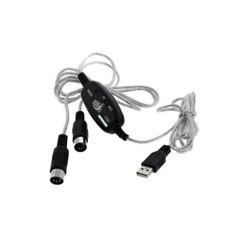
After I opened the adapter (which is available under identical tens different brand names to buy here at Amazon), I saw that the components on the board were missing and the DIN connector were soldered somehow strange. The soldering made, at least in the labeling of the solder points on the board to, no sense to me.
I then googled and came across the part of Mr. Arvydas UK (arvydas.co.uk) encountered on the technical problems of this adapter (Arvydas board saw hair exactly like mine!) Had been described and solved. So I was not the only one, in which the adapter was not working. Since I do not directly on Arvydas page can link here, you must ergoogeln even the page. Here the necessary keywords: "Arvydas cheap USB MIDI cable some self assembly may be required".
Arvydas problem analysis:
The adapter does not correspond to the MIDI standard (to the find by "Electrical Specification for MIDI - MIDI Manufacturers Association" googling!): On the board is missing an optocoupler and a switching diode. The DIN connectors are also not soldered according to the MIDI standard.
Necessary components:
- 1 1-channel optocoupler with 4 pins (. I have a PC817 SOP-4 used for 15 pieces I paid 2 euros on eBay Arvydas used a SFH618-2 DIP-4..)
- 1220 ohm resistor
Non-essential components:
- 1 switching diode 1N4148 or 1N914
The solution (along the instructions of Arvydas with two small additions of me to meet the Midi standard course, all this is no guarantee.):
- Optocoupler to the corresponding point of the solder board U1 - correctly orientated!
- Remove On the board the bridge resistor R11. (Between the two solder points may then there are no longer any connection!)
- A 220 ohm resistor at R5 solder. (A normal resistance should fit easily with a bit of good will)
- The lack of diode D1 can one save. (But who really wants, like me, who must a common 1N4148 or 1N914 diode switching here according to MIDI standard - note orientation - soldering the adapter works well without..)
- If necessary, re-solder the wires of the DIN connector with the board. The result should look like this:
Midi-Out:
- White or green on D + (per DIN connector there are three wires Said wire is either white or green.!)
- Black on D-
- Does not connect red (or according to MIDI standard with G / GND on the board)
Midi-In:
- White or green on IN + (This strand was cut with me from work and had to be extended!)
- Black on IN-
- Red not connect (Really!))
- Adapter with MIDI devices and computer connect and test (with MIDIOX). He should now work and the control lights on the board should all go. Otherwise, debugging is a must!
- If the adapter is working, cover it and find that the four nipples that are held together both plastic lid are all aborted when opened. So both covers with a few windings tape sticking together professionally. Done.
My adapter is working properly since.
All in all, these USB Midi adapter a pretty little electric project. But let's be honest, who has just expects a factory working USB MIDI adapter and professionally even a hobby to do with electronics either, for this adapter would be definitely a bad buy.


![Tomy Aquadoodle pin Two Pack [DVD] (Toys)](https://img.tgreer.com/thumb/85x85/9/7d/97d5b4da5e1354feaa4671aa6db06fdc.jpg)


