
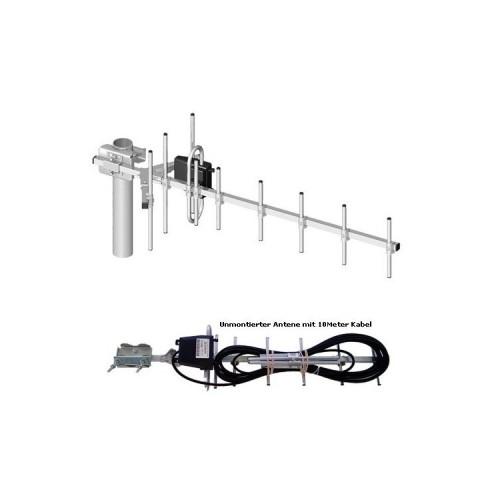
At the University of Applied Sciences South we have the antennas measured by a Rhode and Schwarz vector network analyzer:
Antenna 1:
Delivered high reflection factors (bad VSWR), this read by replacing the balun (-> see Wikipedia) correct.
Antenna 2:
Was much better from the measurement result, but at this one end of the antenna Ringdipols was also isolated.
Through correction of the above deficiencies is lost the warranty, but the antennas are much better. I would point out that all defects caused by the construction of the antenna.
The correction can be made as follows:
Material requirements:
about 15 cm RG58 cable (per antenna),
Solder
Measurement:
Continuity Testers (beeper) or ohm meter,
Tool:
Open-end wrench 7 mm,
Needlenose pliers,
Soldering iron (no 100 watt soldering gun)
Cutters
Cable knife,
possibly phillips screwdriver,
1.1. (With mounted antenna must be so, first a reflector incl. Its holder disassembled) Remove the cover from the terminal box,
1.2. Dismantle the connecting cable (2 Loosen nuts and 4 washers together with the soldered cable pull)
1.3. Measuring the resistance between the screw (continuity check) when a conductive connection exists skip to step 3,
2.1. Dismantle the lower housing shell (this again 2 Release nuts)
2.2. Nuts dipole solve (no need to remove)
2.3. insulating plastic to remove screws (needle-nose pliers, knives, etc.),
2.4. Dipole secure (tighten well) again,
2.5. Attach Attach the lower housing shell, with 2 nuts,
3.1. the bypass line of the balun (measured: tuning at 1100 MHz) is too short. When using RG58 cable of the shielded part of the cable must be 12.4 cm long. Important: Only use 50 ohm cable.
3.2. The new balun installing, the cables connect to the antenna (the 4 washers with the 2 nuts fasten)
3.3. Replace the cover and possibly mount the reflector again.
Also it is advisable to cut the connecting cable (if possible -> reduction in attenuation of the connection cable).


![Hama wire antenna (dipole) 1.5 m, coax [Amazon Frustration-Free Packaging] (optional)](https://img.tgreer.com/thumb/85x85/0/44/0448a2756a918132.jpg)


