with us the electrician install this dimmer than stairwell relays TLZ function. But the 230 was (effectively), 50Hz (ie mains) connected by the buttons on the + E1 input, E2 was on N. I wanted to run for the yard light in MMX or ER mode the dimmer, again just as connected but the desired function is not (not ER, with MMX light is tackled without dimming and remained attached) went.
The documentation can not see what input what is good man - because then "Both central inputs are active" is, for example, and in the circuit diagram "central ON" / "Central off" to the buttons for + E1 and F1 +. Who has the random manner not overlooked, can conclude now that + E1 + F1 and the central inputs and A1 + hence the control voltage. But when I put the cable of the buttons on + A1 (-A2 course on N) concerned, for whatever reason, not yet. There was tinkering just haphazard and the switch depends mind in addition to the main fuses, you do not get the conductor rail (unsecured and without earth leakage) readily stress relief. In such an environment, you should connect a device actually and it should work, but if you can be 100% sure already in the wiring not ...
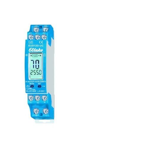
Also you can not really see the microphysical description 8-230V UC, of whatever kind must be the control voltage applied. UC is probably for "universal current" but what is to be exactly ... no idea. Our mains voltage swings between +/- 320V, so do not talk, you can be sure that that's right. Whether I in my attempts to A1 + tax at the normal AC line voltage, somehow a piece of insulation had jammed, and it therefore did not work, or if it actually does not work with the mains voltage, I do not know.
In MMX / HE mode I brought the dimming function for the first time to run, when I held a (new) 9V battery + A1 and -A2. Before that I had taken an old, rusted battery, which although could turn E1 + TLZ in mode, but not + A1. The inputs behave so ever not equal. After seeing so after hours of trying only to a DC voltage could switch the + A1 input, I decided short hand upstream rectifier. So did me a diode, two resistors (200K, 22K) and a 10uF capacitor built a simple rectifier which outputs about 20V, with approximately 1s rise / fall time when turning on / off. And it did not work! Apparently the dimmer switch has an off-negligible internal resistance and the 200K were too much. I then still a transformer upstream and 200K bridged with 15, only then we went. I did not want to create a 230V DC voltage, so the effort ... Now therefore depends a lunchbox next to the dimmer switch, but it works.
There is the whole thing obviously a significant number of sources of error and therefore would require a rather more detailed examination not hurt.